Milestone 1
For this milestone, we have 2 important goals to achieve:
-
A robot that successfully follows a line of black tape.
-
A robot that successfully traverses a grid of black tape in a figure eight.
To complete this milestone, we first had to add line sensors to our original lab 1 prototype. Learn more about line sensors here: line sensors. We then made the robot follow the line of black tape before we were able to make it turn, and then subsequently make it go in a figure 8 pattern.
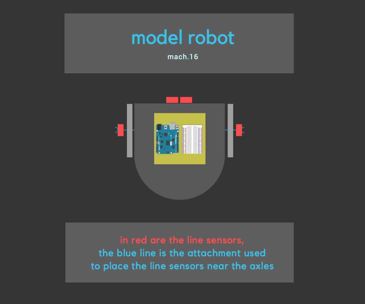
Here is a diagram of our line sensor placement on the prototype:
1. Following a line
In order to make the robot follow a straight line, we first tested the different values the line sensor generates. We picked the threshold value that separates black and white lines to be 750.
- If threshold > 750 black else white
The line following sensors were placed on the front middle side of the robot and were tied together to make the data captured by both as similar as possible.
The algorithm compares the values generated by the the left and right middle sensors to enable the forward motion.
Pseudocode
  If (middleLeftVal > 750 && middleRightVal < 750) {
    move right with max speed
    slow down left
  }
  If (middleLeftVal < 750 && middleRightVal > 750) {
    move left with max speed
    slow down right
  }
  If (middleLeftVal > 750 && middleRightVal > 750) {
    move both with max speed
}
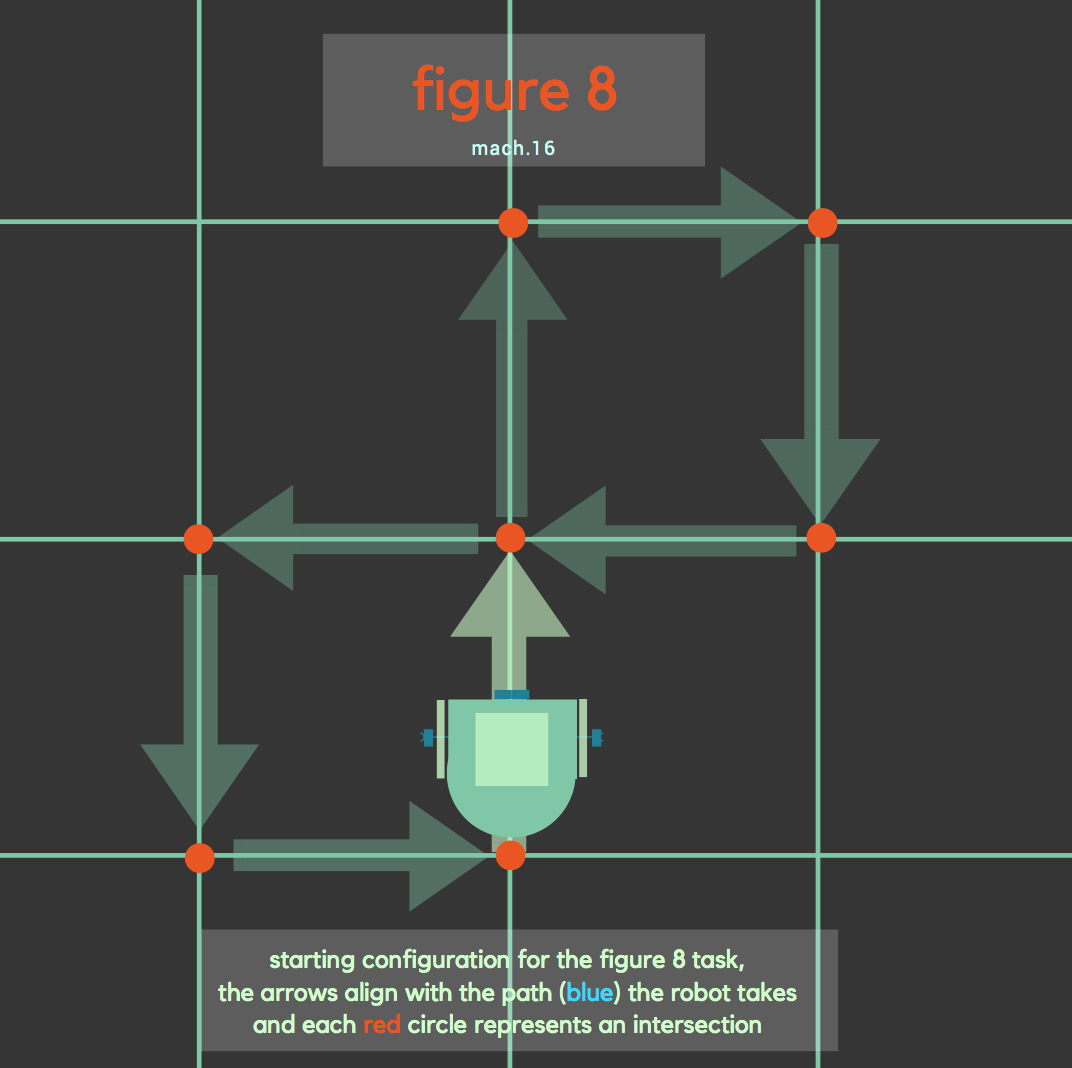
2. Making a figure 8
The following diagram shows how we want to configure our robot to make a figure 8 within the grid.
We followed the same procedure as line following to make the robot follow a straight line path, however, we changed the threshold level to 800 from the 750 we previously had, just an adjustment for the two sensors outside each axle.
The next step was to figure out how to make the robot turn when it reaches an intersection. An intersection is detected when both side sensors are above black lines. In our code this is detected by the following condition. Both left and right outer sensors must be over black lines.
((outerLeftVal > threshold) && (outerRightVal > threshold))
Once the robot detects the turn and knows which way to turn, either the rightturn() or leftturn() functions are executed. Turning right involves setting the left servo angle to 180 and the right servo angle to rightServoMap(0). Turning left sets the left servo angle to 0 and the right servo angle to rightServoMap(180). The rightServoMap function subtracts the angle from 0, because the orientation of the right servo is opposite to that of the left servo. In essense, turning right involves rotating the left servo, and turning left involves rotating the right servo.
int rightServoMap(int angle) {
  int newAngle = 180 - angle;
  return newAngle;
}
However, to properly navigate the map, the robot needs to know when to start and stop turning. A turn is executed when an intersection is detected and the current move is a turn.
while ((analogRead(outerLeftPin) < threshold) && (analogRead(outerRightPin) < threshold)){
    leftServo.write(leftServoAngle);
    rightServo.write(rightServoAngle);
    delay(delayTime);
}
The robot turns for a set time, and then enters this while loop. Which essentially keeps turning until the front sensors are above a black line, which means the robot is on the line it is trying to turn on to. At this point, the robot is free to go straight and continue its line following algorithm.
- Below is a pictorial reprsentation of the turning process:
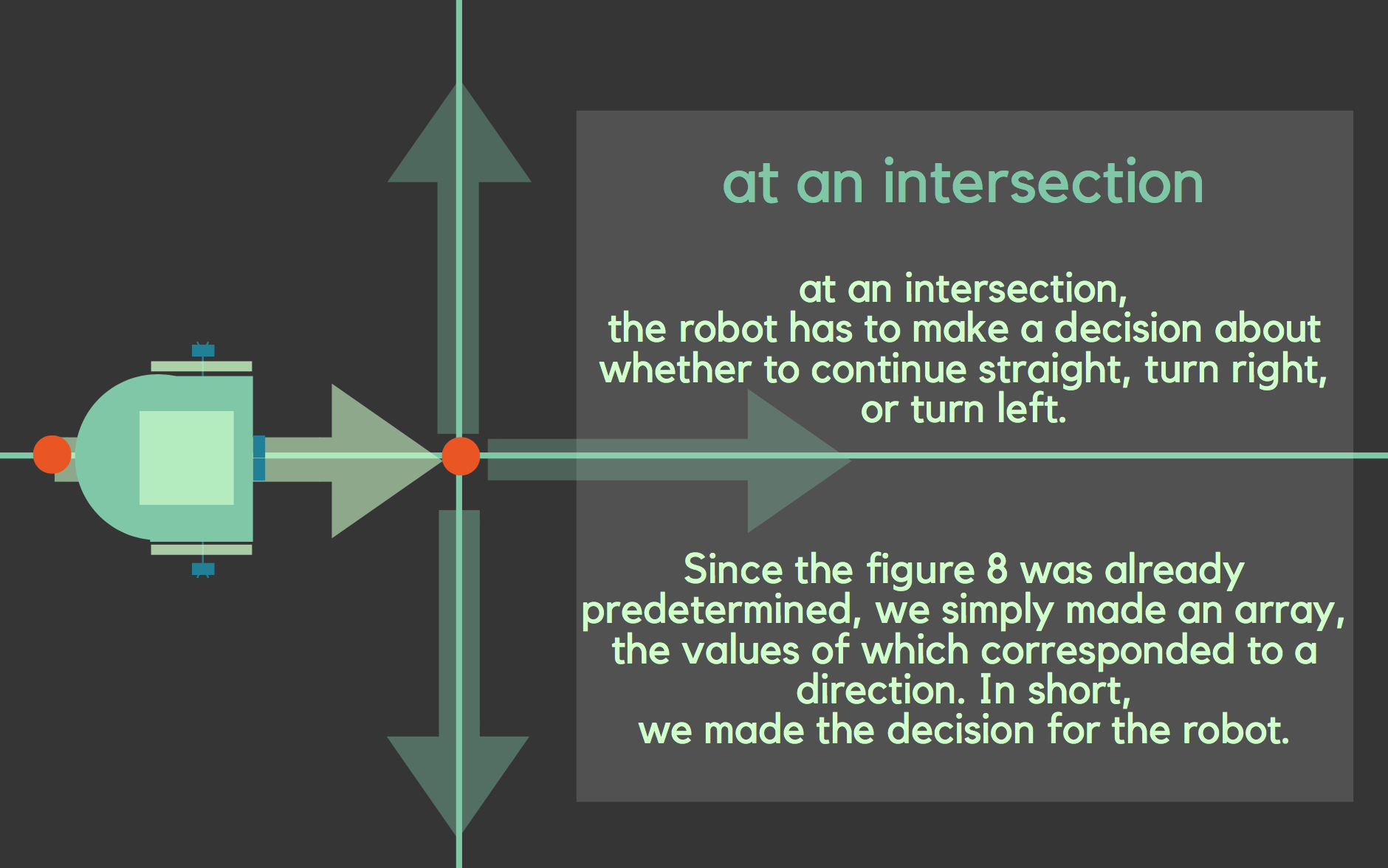
At each intersection, the robot has to decide whether to go straight, make a right turn, or a left turn.
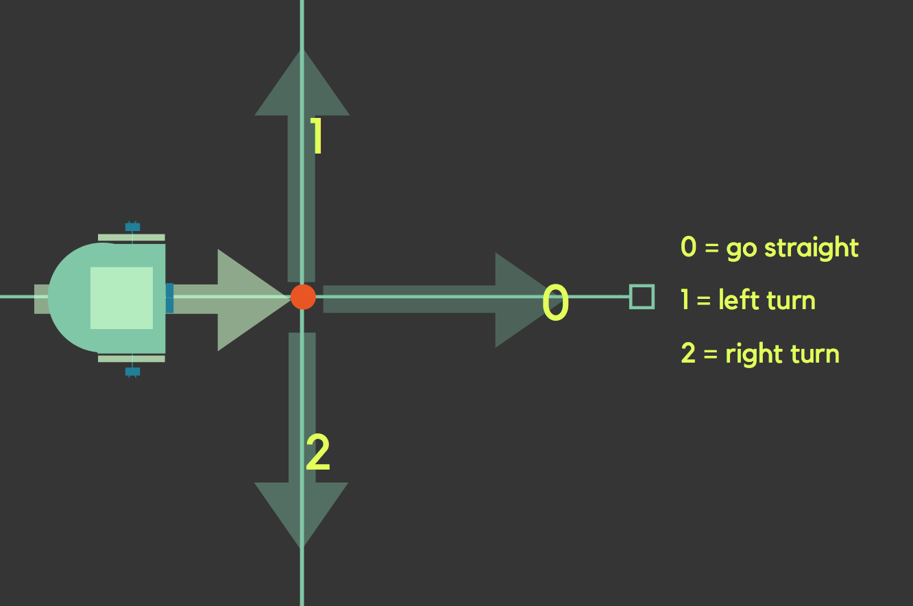
We made the decision for the robot by giving each possible route a number value, as seen below.
Then we made an array for the complete set of values that corresponded to a figure 8, which can be seen in the next diagram.
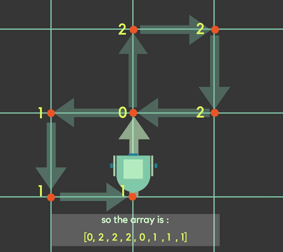
Thus by iterating through each value of the array, the robot will make a figure 8, and once it finishes one cycle, we coded such that the robot will restart a new cycle by starting the array once more, and continue in a figure 8 path.
Challenges(Troubleshooting)
In coding the line following portion of the robot, we had to maintain robot’s ability to stay on the line. In the implementation, our turning is based on which sensor is on the black line. If both sensors are over the black line, then the robot moves forward. If the left sensor is off the line, then the right servo motor slows down and if the right sensor is off the line, then the left servo motor slows down. In keeping the robot on the line, we had to tune the duration of the turn and the degree of the turn, to make the robot return to the line as soon as possible.
In the figure eight portion of milestone 1, we added line sensor by the wheels aligned to the axis of the wheels since we determined that once we arrived at the intersection that the robot will turn about the center of its wheels axis. In first testing of the robot with intersection, we found out that we were hooking up one of the outer line sensors incorrectly. One issue we came upon was at the first intersection where the robot is supposed to go forward, the robot would count the intersection multiple times. To solve this problem, we increased the time the robot goes forward upon reaching the intersection. The next problem we came upon was that at the intersections where the robot must turn, the robot would turn multiple times. We first included a preset amount of time for which the robot turns and a while loop for when the robot completes the turn. This did not solve the problem. Next, we tried making the robot go forward for some small time after the turn. This did not completely solve the problem, so we tried extending the time for which the robot travels forward after the turn which solved our last problem.
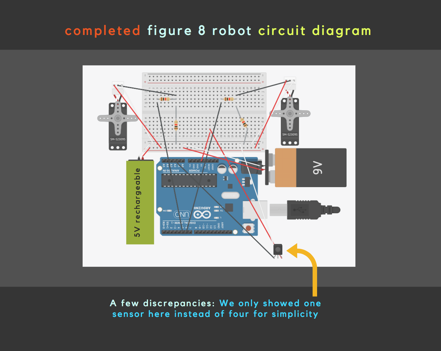
Final Circuit Diagram